
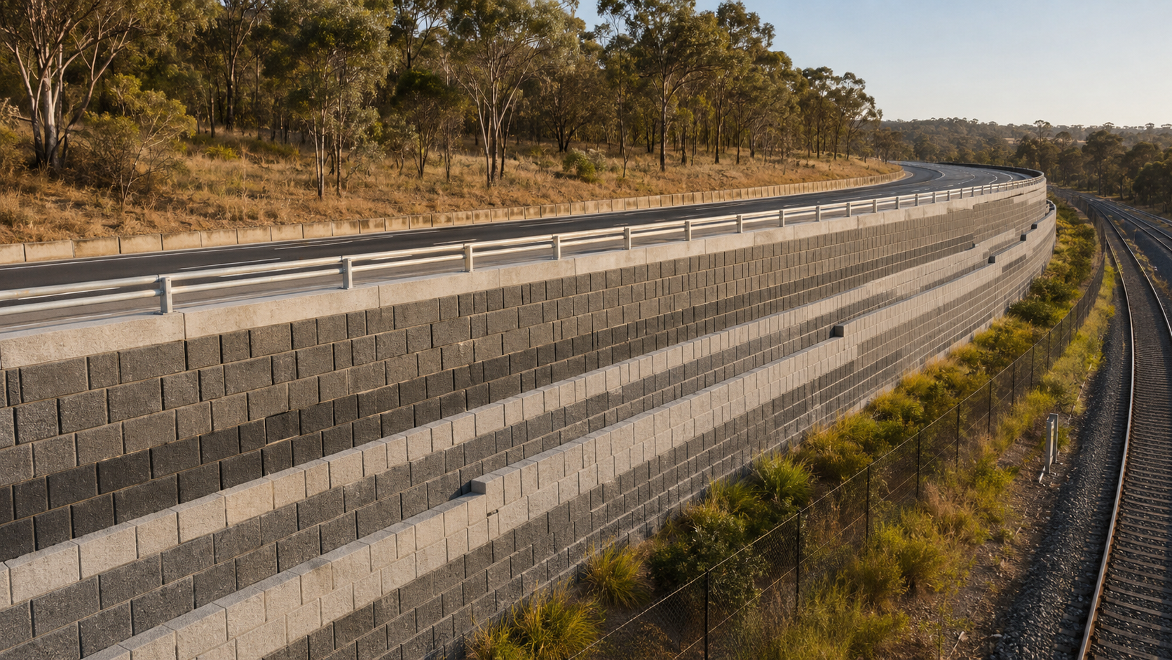
Less surface footprint
Useful where boundaries, haul roads, plant, waterways or services make a conventional batter impractical.
High-stiffness, integrally formed HDPE reinforcement for near-vertical walls, bridge approaches and steepened earth structures—selected around the design load, connection, fill and design life—not ultimate tensile strength alone.
Engineer-led selection · Project-direct supply · Australia-wide support
Technical resources · 1 file
Current product documents are available here. Selection guidance, installation context and full technical detail continue below.
Reinforcement restrains lateral deformation and creates a coherent soil–geogrid mass. The facing is then selected for connection, durability, tolerance and appearance.
Surface land retained. A near-vertical face can preserve a platform, road corridor or development envelope that a safe batter would consume. The reinforced zone still requires space behind the face and must be protected from future excavation.
Useful where boundaries, haul roads, plant, waterways or services make a conventional batter impractical.
An extensible reinforced mass can accommodate differential movement better than many rigid gravity solutions—within the facing system’s limits.
Compacted engineered fill carries compression and shear; the grid supplies tensile resistance where the soil cannot.
The Kontain KUG range covers six integrally formed HDPE uniaxial geogrids. Values shown are manufacturer-published machine-direction index properties, supported by product certification for supply.
| Kontain grade | 2% strain | 5% strain | Ultimate | Ultimate strain | Junction efficiency | Flexural rigidity | Standard roll |
|---|---|---|---|---|---|---|---|
| KUG-60 | 16 kN/m | 31 kN/m | 60 kN/m | 11.5% | 93% | 530,000 mg·cm | 1 or 2 m × 100 m |
| KUG-80 | 23 kN/m | 44 kN/m | 80 kN/m | 11.5% | 93% | 1,100,000 mg·cm | 1 or 2 m × 50 m |
| KUG-120 | 35 kN/m | 65 kN/m | 120 kN/m | 11.5% | 93% | 6,000,000 mg·cm | 1 or 2 m × 50 m |
| KUG-160 | 47 kN/m | 93 kN/m | 160 kN/m | 11.5% | 93% | 8,500,000 mg·cm | 1 or 2 m × 50 m |
| KUG-180 | 52 kN/m | 104 kN/m | 180 kN/m | 11.5% | 90% | 9,400,000 mg·cm | 1 or 2 m × 50 m |
| KUG-200 | 58 kN/m | 116 kN/m | 200 kN/m | 11.5% | 90% | 9,600,000 mg·cm | 1 or 2 m × 50 m |
COMMON PROPERTY BASIS HDPE; minimum carbon black 2%; ASTM D6637 tensile; GRI GG2-87 junction efficiency; ASTM D1388 flexural rigidity.1
DURABILITY DATA Published results include 98% UV resistance to ASTM D4355, 100% oxidation resistance to EN ISO 13438 and Pass to WashDOT T926 brittleness testing.1
Short-term tensile index value. Use as the numerator only when its statistical basis and test method suit the adopted design method.
Useful indicators of early-load stiffness. They do not replace isochronous curves, creep strain prediction or whole-wall deformation analysis.
Derive from creep-rupture regression for the exact polymer, profile, manufacturing route, design temperature and required life.
Match test fill, maximum particle, angularity, lift thickness, compaction energy and construction plant to the project method.
Assess oxidation, stabilisation package, stress cracking, pH, contaminants, temperature and exposure before burial.
The facing connection or soil interaction may govern before grid rupture. Test the nominated face, connector and project fill.
Apply transparent reduction factors to the published ultimate tensile strength using RF = RFCR × RFID × RFD.4 The resulting value supports reinforcement selection within the adopted wall-design method.
34% of published ultimate strength remains after the selected reductions.
Grade, spacing and length are outputs of a limit-state workflow. Geometry-only rules can help early feasibility, but they cannot resolve weak foundations, water, unusual surcharge, compound failure or deficient connections.
Foundation strength, compressibility, retained soil, groundwater and credible pore-pressure conditions.
Self-weight, surcharge, traffic/barrier loads, seismic demand, services, impact and staged construction.
Sliding, eccentricity, bearing capacity, settlement and the geometry of the complete reinforced block.
Rupture, pull-out, vertical spacing, embedment beyond the failure surface and local overstress.
Connection capacity at representative confinement, facing stability, drainage and construction tolerance.
Compound/global slip surfaces, deformation, creep strain, design life and construction sequence.
Current MRTS06 defaults to a water table at two-thirds wall height unless compliant drainage or free-draining fill justifies relaxation, and requires explicit global stability assessment.2
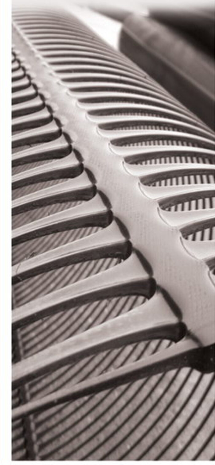
KUG geogrids are extruded, punched, heated and longitudinally oriented to create continuous ribs and integral junctions. The primary machine direction is installed perpendicular to the wall face.
Kontain combines published KUG product data with project-specific selection, documentation and construction support for reinforced-soil structures.
HDPE has a broad buried-soil chemical window and robust integral junctions, but generally needs a larger creep reduction than high-tenacity PET. Steel remains extremely stiff and proven, but corrosion assumptions must be controlled for the full life of the structure.
| Design issue | Extruded HDPE | Coated PET | Steel strip / mesh |
|---|---|---|---|
| Stiffness + creep | Moderate stiffness; larger creep reductionUse product-specific long-term data and strain checks. | High stiffness; flatter creep responseEfficient where deformation control is critical. | Very high stiffnessNo polymer creep; metal-loss design still applies. |
| Chemical exposure | Broad pH toleranceTfNSW lists pH 3–12 for HDPE reinforced fill. | Hydrolysis needs controlTfNSW lists pH 4–9; polymer quality matters. | Electrochemistry governsResistivity, pH, salts, water and stray current require control. |
| Deterioration mode | Does not rustStill verify oxidation and stress-cracking resistance. | Does not rustVerify coating damage and long-term hydrolysis. | Corrosion is credibleGalvanising and sacrificial thickness depend on actual exposure. |
| Practical fit | Aggressive fills and robust handlingStrong option where pH range and corrosion avoidance matter. | High stiffness in controlled chemistryAttractive for movement-sensitive applications. | Controlled proprietary systemsAppropriate where corrosion design and monitoring are accepted. |
TfNSW’s current construction specification lists pH 3–12 for HDPE and 4–9 for PET, with separate chemical and electrical limits for galvanised steel.3 FHWA treats metallic reinforcement corrosion as a design and asset-management issue.6
A strong grid can be defeated by wrong orientation, poor fill, slack, an unverified connection, excessive near-face compaction or drainage that does not work.
Proof-excavate, treat weak zones and confirm the design ground model before the levelling pad starts.
Build the first course or panels level and true. Face alignment errors compound rapidly with height.
Install the drainage aggregate, filter transition, collector and outlets before the reinforced zone can trap water.
Use controlled lifts. Remove oversized, angular or deleterious material that falls outside the design envelope.
Orient machine direction into the fill, complete the approved facing connection, pull taut and pin temporarily.
Place fill without creating slack. Maintain the specified cover before plant travels over reinforcement.
Compact parallel to the face, use light plant near panels and avoid braking, turning or rutting over reinforcement.
Record grade, roll, level, length, orientation, connection, damage repairs, fill and test results at each lift.
MRTS06 prohibits splicing or joining synthetic reinforcement in its primary strength direction.2
Maintain at least 150 mm of fill before tracked plant or vehicles operate over the reinforcement.2
Uniaxial strength is directional. Roll direction normally runs perpendicular to the face; follow the certified reinforcement schedule.
Under MRTS06, plant over 1500 kg stays at least 2 m from panels unless the design allows otherwise.2
Tension flat before cover and place fill so displacement or slack is not reintroduced.
Detail outlets, filters, redundancy and maintenance. Shape daily work to drain away from the face.
Grading, angularity, shear strength, pH and compaction can change pull-out, damage and stability.
Penetrations, culverts and future excavation require designed transitions—never shorten or sever a reinforcement layer informally.
A useful early review needs more than height and square metres. Send available information—even if incomplete—and mark assumptions that still need confirmation.
Wall height, tiers, setbacks, curves, toes, crests and reinforcement-space boundary
Boreholes, foundation strength, settlement, global geology and groundwater
Traffic, barrier, rail, buildings, stockpiles, seismic, impact and construction surcharge
Block or panel system, connection detail, tolerances, batter and architectural finish
Grading, Dmax, angularity, unit weight, shear strength, pH and source variability
Design water level, filters, outlets, flood/scour exposure and maintenance access
Design life, design temperature, contaminants, oxidation and exposure during storage
Services, culverts, abutments, corners, penetrations and future excavation controls
Principal specification, road/rail authority, registration and independent review needs
Programme, roll width/length, laydown area, lifting limits, ITPs and hold points
KUG selection and project advice are supported by published product data and the relevant Australian and international design framework.
Kontain KUG Series Technical Data SheetPublished KUG product properties, durability results, reduction factors and roll dimensions.
Queensland TMR MRTS06 Reinforced Soil Walls — November 2025Design life, water, geosynthetic evidence and construction controls.
TfNSW TS 02165:1.0 Construction of Reinforced Soil StructuresEffective 26 November 2024; fill pH, steel exposure and construction QA.
FHWA-HIF-24-002 — Design and Construction of MSE WallsCurrent-practice MSE design and construction manual; published August 2023.
AS 4678-2002 Earth-retaining structuresAustralian design criteria and guidance; apply current amendments and project requirements.
FHWA NHI-09-087 — Corrosion/Degradation of Soil ReinforcementsCriteria and monitoring context for steel corrosion and geosynthetic degradation.