
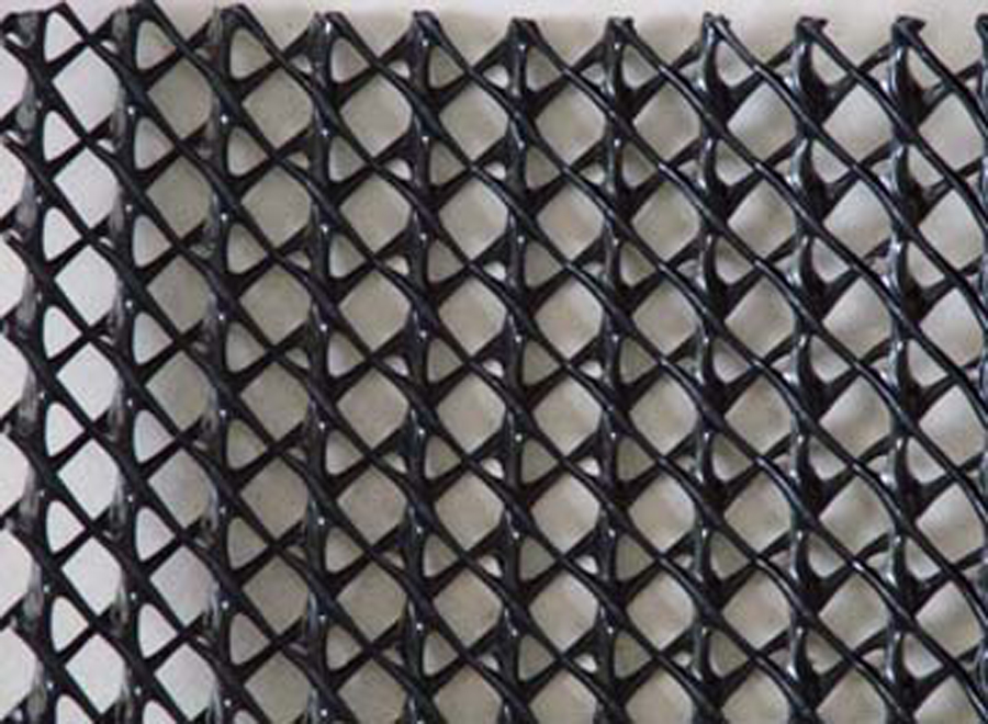
 BARE CORE
KDRAIN TN
Triplanar HDPE geonet
Unlaminated three-dimensional core for applications where the adjacent geosynthetics are designed and installed separately.
KTN-50 · KTN-55 · KTN-60 · KTN-63 · KTN-70KDrain Series · triplanar drainage systems
HDPE triplanar geonet cores and double-sided geotextile composites selected from the required flow, normal stress, gradient, boundary materials and long-term exposure—not thickness alone.
Published flow values are short-term index data at 480 kPa, hydraulic gradient 1.0 and 15 minutes. Final design should use ASTM D4716 testing under the actual project conditions and a site-specific long-term reduction basis.
Technical resources · 1 file
Current product documents are available here. Selection guidance, installation context and full technical detail continue below.
Kontain private-label range
The grade code identifies construction, facing polymer and nominal thickness. The current TDS data represent PET facings; PP nonwoven alternatives are available with separate order-specific data and certification.
BARE COREKDRAIN TN
Unlaminated three-dimensional core for applications where the adjacent geosynthetics are designed and installed separately.
KTN-50 · KTN-55 · KTN-60 · KTN-63 · KTN-70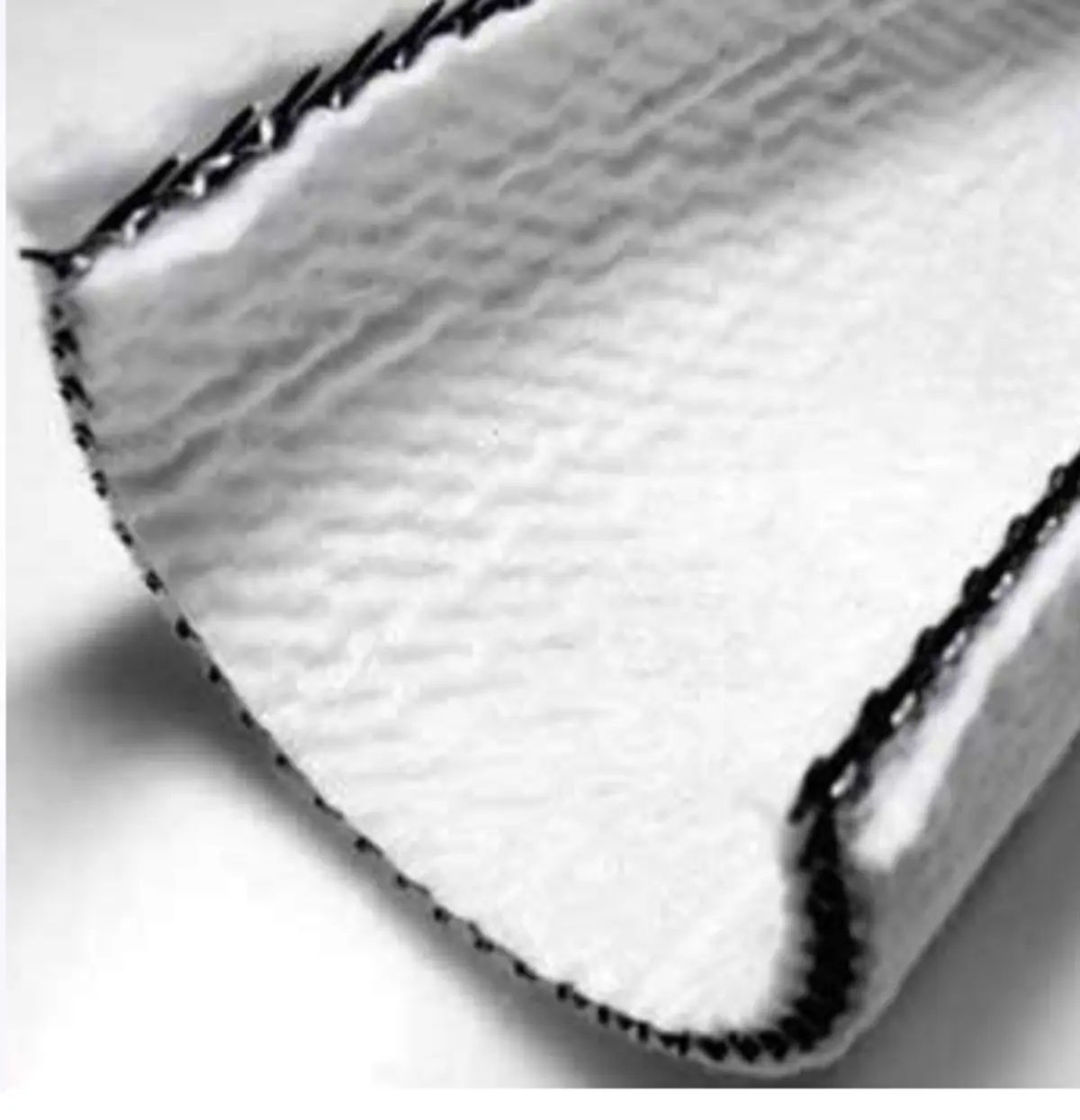 DOUBLE-SIDED
KDRAIN DC150
Triplanar core factory-laminated to 150 g/m² PET filament nonwoven geotextile on both faces for filtration, separation and core protection.
KDC150-PET-50 through KDC150-PET-70HEAVIER FILTERKDRAIN DC200
Heavier double-sided PET nonwoven construction represented by the current TDS. PP facings can also be manufactured but require their own project schedule and supporting data.
KDC200-PET-50 through KDC200-PET-70System position matters
The same core can behave differently between rigid platens, geomembrane, geotextile, soil or waste. The project test stack should reproduce the actual upper and lower boundaries, normal stress, gradient, liquid and installation orientation.
Applications
Drainage demand, available head, outlet spacing and system reliability govern whether a geocomposite is appropriate and which site-specific tests are justified.
Convey leachate above the primary liner, subject to site liquid, intrusion, biological loading and long-term transmissivity verification.
Provide rapid in-plane flow between barrier layers while retaining an auditable factor of safety at the design normal stress.
Transmit infiltration or gas beneath cover systems, with root and biological clogging risk selected for the actual cap profile.
Relieve groundwater and uplift pressure beneath ponds, reservoirs and containment liners using the complete boundary condition in testing.
Replace thick granular drainage zones where filtration, connection, outlet spacing and long-term flow are designed together.
Drain roof decks, tunnels, buried walls and capillary-break profiles where load, gradient, water quality and outlet continuity are defined.
Evidence boundary
Independent sample testing is useful, but the tested specimen, boundary condition and duration must stay attached to every stated result.
Two machine-direction specimens at 480 kPa, hydraulic gradient 1.0, 15-minute seating and rigid plates. Individual results were 1.66 × 10⁻³ and 1.76 × 10⁻³ m²/s.
Five specimens ranged from 549.9 to 702.0 kPa. This is short-term fixed-plate compression behaviour of the submitted bare geonet sample—not long-term flow retention.
The report does not identify a finished Kontain grade, geotextile laminate or production population. It is supporting sample evidence, not a MARV or a transferable design value.
GRI-GN4 expressly covers biplanar geonets and says it does not cover triplanar geonets or drainage composites made from them. KDrain is therefore not represented as GRI-GN4 compliant. The TRI fixed-plate compression result is also not directly comparable with GN4's movable-plate biplanar requirement.
Review GRI-GN4Published technical data
Values below reproduce the current supplier data supplied to Kontain. Confirm the final project schedule, certificate and test boundary before procurement.
| Property | Method | Unit | KTN-50 | KTN-55 | KTN-60 | KTN-63 | KTN-70 |
|---|---|---|---|---|---|---|---|
| Nominal thickness | ASTM D5199 | mm | 5.0 | 5.5 | 6.0 | 6.3 | 7.0 |
| Density | ASTM D1505 | g/cm³ | ≥0.95 | ≥0.95 | ≥0.95 | ≥0.95 | ≥0.95 |
| Carbon black | ASTM D4218 | % | 1.5–3.0 | 1.5–3.0 | 1.5–3.0 | 1.5–3.0 | 1.5–3.0 |
| MD tensile strength | ASTM D7179 | kN/m | ≥8 | ≥9 | ≥10 | ≥11 | ≥12 |
| Published compressive strength | ASTM D6364 / D1621 | kPa | 400 | 400 | 500 | 500–550 | 500–600 |
| Bare-core flow @ 480 kPa, i=1.0, 15 min | ASTM D4716 | L/min/m | ≥90 | ≥100 | ≥110 | ≥124 | ≥140 |
| Property | Method | Unit | 50 | 55 | 60 | 63 | 70 |
|---|---|---|---|---|---|---|---|
| Finished-composite flow @ 480 kPa, i=1.0, 15 min | ASTM D4716 | L/min/m | ≥30 | ≥35 | ≥40 | ≥45 | ≥55 |
| Equivalent published transmissivity @ i=1.0 | Calculated from declared flow | m²/s | ≥5.00×10⁻⁴ | ≥5.83×10⁻⁴ | ≥6.67×10⁻⁴ | ≥7.50×10⁻⁴ | ≥9.17×10⁻⁴ |
| Ply adhesion | ASTM D7005 | N/m | ≥170 | ≥170 | ≥170 | ≥170 | ≥170 |
| Standard roll widths | Nominal | m | 4 / 5 / 6 | 4 / 5 / 6 | 4 / 5 / 6 | 4 / 5 / 6 | 4 / 5 / 6 |
| Standard roll lengths | Nominal | m | 30 / 40 | 30 / 40 | 30 / 40 | 30 / 40 | 30 / 40 |
Facing data: the current TDS represents PET facings. The 150 g/m² PET values are 550 N grab, 9 kN/m wide-width tensile, 250 N tear and 1.6 kN CBR puncture. The 200 g/m² PET values are 710 N grab, 12 kN/m wide-width tensile, 330 N tear and 2.1 kN CBR puncture. PP alternatives require separate order-specific data.
Hydraulic limitation: the published composite flow data are at one load, one gradient and 15-minute seating. They are not q100, do not include project boundaries and do not establish allowable long-term flow.
Preliminary drainage design tool
The tool exposes the selected test value and every reduction factor. It does not convert 15-minute catalogue data into a certified long-term design value.
35 L/min/m at 480 kPa and i=1.0; published construction uses PET geotextile facings. The selected transmissivity is multiplied by the entered gradient for screening; verify non-linear behaviour by testing at the project gradient.
The catchment method assumes each metre of drainage width receives flow from the entered upslope drainage length. Confirm the governing project hydrology and drainage geometry.
GRI-GC8 supplies application ranges for chemical and biological clogging. Creep, intrusion, construction and factor-of-safety defaults shown here are conservative screening assumptions—not tested KDrain values or prescribed GRI-GC8 numbers.
Select Enter project-specific test value to replace catalogue transmissivity, and overwrite any suggested reduction factor when supported by testing. A published-data pass remains a preliminary screen, not design qualification.
Project-specific performance testing
Kontain can coordinate drainage-composite qualification through a partner laboratory. For higher-risk work, the programme should move beyond catalogue flow and reproduce the design stack.
ASTM D4716 / GRI-GC8 using actual normal stress, gradient, boundaries, liquid, orientation and finished composite.
Core-only creep deformation, typically to 10,000 hours under GRI-GC8, to derive a product- and condition-specific RFCR.
Project filter compatibility, geotextile intrusion, interface shear and outlet/overlap detailing.
Representative-liquid immersion and a go/no-go polymer review where leachate, brine, process water or aggressive chemistry is present.
Project-direct supply
Standard roll formats are 4, 5 or 6 m wide and 30 or 40 m long. Lengths and core thickness can be customised, including cores up to 8 mm, subject to production and freight review.
Roll count is a geometric estimate only. Kontain will confirm roll mass, outside diameter, container utilisation, production minimum and freight plan before issuing pricing.
Need a defensible drainage basis?