
SECTION 01
Use the right installation detail
A geosynthetic clay liner (GCL) works as a system: bentonite, geotextiles, overlaps, adjacent materials and confinement. Good material can still leak or move if one of those elements is wrong.
Scope and application
This guide covers Kontain standard and composite-base reinforced GCLs, with or without an integral polyethylene (PE) laminate, and project-selected polymer-modified bentonite. It addresses earth-lined ponds, containment cells, caps and similar buried systems. It is general installation guidance, not a project design or a substitute for the supplied grade’s technical data sheet (TDS). Building waterproofing, exposed liners and specialist vertical systems need separate details.
Four controls that apply throughout
- Confirm the actual product, face orientation, factory seam treatment, liquid chemistry and accepted installation schedule before opening rolls.
- Place GCL on accepted subgrade, flat and without tension. Keep plant off exposed GCL and protect against premature hydration.
- Maintain direct GCL-to-GCL contact at bentonite overlaps. For laminated material, follow the supplied overlap detail and keep PE out of the specified GCL contact plane.
- Inspect seams and details before concealment, then place continuous, compatible confinement promptly. A loose laminate lap is not a welded membrane seam.
Which document controls?
Use the approved project specification, drawings, installation method and construction quality assurance (CQA) plan together with the order-specific TDS and this guide. Resolve any conflict with the designer and Kontain in writing before proceeding; do not select whichever requirement is easiest. A general guide does not authorise a change to an existing approved liner system.
Reading the dimensions
Slope ratios are written vertical:horizontal: 1V:4H means one metre vertically over four metres horizontally. Lap widths are the actual overlap remaining after alignment and movement, not the width of a factory treatment strip. Numerical values labelled as guide baselines require confirmation for the supplied grade and project; larger project requirements govern.
Document control
Kontain GCL Installation Guide • Issue 1, Revision 2 • 17 October 2026. This online guide covers the published unlaminated and 0.2 / 0.5 mm PE-laminated range. Existing project approvals and order-specific requirements continue to govern supplied material.
SECTION 02
Select the construction and chemistry
Use descriptive product families for selection. The order must still identify the exact construction, declared properties and manufacturing lot.
Product families
| Family | Construction and use | Installation consequence |
|---|---|---|
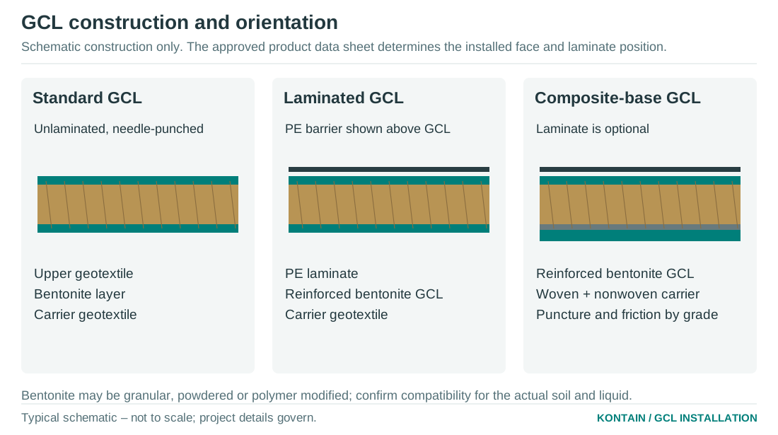
| Standard GCL | Reinforced bentonite layer between geotextiles; commonly a woven carrier and nonwoven cover. | Use fine, smooth contact surfaces and the accepted grade-specific protection schedule. |
| Composite-base GCL | Woven reinforcement combined with a nonwoven base component, with the face construction confirmed by the TDS. | Can improve robustness and interface behaviour. Verify the exposed face, puncture resistance and hydrated shear performance. |
| Laminated GCL | An integral PE barrier on the nominated GCL face; standard or composite base may be selected. | Normally place laminate towards the contained liquid. Follow the supplied joint detail for the 0.2 or 0.5 mm PE option, with specified GCL contact and confinement. |
| Polymer-modified option | A selected polymer formulation incorporated into the bentonite system. Available with suitable base and laminate configurations. | Select and test for the actual soil, hydration water and service liquid; use compatible seam accessories. |
Rolls and cores
A common supply format is 5 m × 30 m, giving 150 m² gross area per roll before overlaps, cuts and waste. Custom widths and lengths can be arranged, subject to production and transport. Plastic or steel cores are available to client preference. Confirm clear bore, core length, stiffness, end condition and gross roll mass for every order; neither a nominal diameter nor a core material establishes lifting capacity.
Granular or powdered bentonite
Both can be supplied. Granular bentonite generally produces less airborne dust during handling than fine powder, which can make site control easier. It is not dust-free and its hydraulic performance is not automatically better. Powder may suit a specified core or seam treatment. Base the choice on proven product performance, the project specification and the safety data sheet (SDS), not particle form alone.
Dust and housekeeping
Handle accessory bentonite close to the work, avoid pouring from height and protect against wind. Follow the SDS for respirable dust and any crystalline-silica content, eye protection and respiratory controls. Do not suppress dust by wetting unconfined GCL or prepared seams. Keep bentonite out of drainage layers; wet spills are slippery.
SECTION 03
Plan the work before delivery
Set the product, construction sequence and inspection hold points before the crew arrives. Most installation problems are easier to prevent at this stage.
Designer’s requirements
- Confirm hydraulic duty, allowable leakage, maximum head, service life, seasonal exposure, groundwater uplift, gas generation and the role of each liner layer.
- Accept subgrade and cover materials, their chemistry, grading, particle shape, moisture condition, density, thickness and erosion controls.
- Check internal and interface shear, slope veneer stability, settlement, anchorages, toe restraint, drawdown and construction loading.
- Issue seam, penetration, structure, repair and transition details, plus any welding and membrane testing specification.
- Define hydration and commissioning requirements, including compatibility testing and any controlled prehydration.
Installer’s preparation
- Provide a panel layout with roll direction, seam sequence, crest-to-toe panels, end-lap positions, anchor trenches and access routes. Stagger end joints; avoid four-panel junctions.
- Agree daily deployment limits based on weather, inspection availability and cover-placement capacity. Identify temporary runoff diversion and secure overnight protection.
- Prepare a task-specific lifting and deployment method: plant capacity at working radius, ground bearing, roll gross mass, rated accessories, core compatibility, exclusion zones and communication.
- Confirm trained personnel, cutting boards, spare blades, compatible bentonite, repairs, soft ballast, temporary covers and spill controls. Welding requires a qualified crew and approved procedure.
- Plan a representative trial where aggregate, compaction, equipment or seam geometry is unfamiliar. Inspect the GCL after trial loading before accepting the method.
Quality documentation
Retain current TDS, SDS, roll/lot register, certificates of analysis, manufacturing quality-control records, agreed conformance tests and the installation guide adopted for the order. Verify the actual laboratory method and accreditation scope where accredited testing is specified. A laboratory logo, generic certificate or product-family brochure does not prove the delivered lot complies.
Who releases the work?
The installer records and checks the installation. The nominated CQA inspector accepts the agreed hold points; the designer resolves design departures. Kontain confirms supplied construction and product-specific details. Confirm these roles for the project so work is not covered while an acceptance decision is still outstanding.
SECTION 04
Unload, handle and store rolls
A core is part of the handling arrangement, not a lifting certificate. Size every component for the actual supported or cantilevered configuration.
Receiving inspection
- Check roll number, lot, product construction, laminate thickness, dimensions, gross mass and order schedule before unloading.
- Inspect wrapping, roll ends and accessible core bore for tears, water ingress, displaced material, crushing, cracks, corrosion damage, distortion or obstruction. Photograph defects against the roll number.
- Quarantine wet, damaged or unidentified rolls for a written disposition. Do not assume apparently dry external wrapping proves a dry core.
Safe lifting and deployment
- Use an engineered, rated spreader beam with a compatible full-length mandrel, or an approved core-prong system designed for its engagement and support arrangement. The lowest-rated component and the plant’s capacity at the actual radius govern.
- Check mandrel outside diameter against the measured clear core bore, including ovality and insertion clearance. Do not force a mandrel through a damaged core.
- Keep the roll level, control swing and use the planned exclusion zone. No person may stand beneath a suspended roll or between the roll and a fixed object.
- Never improvise with a bare forklift tine, lift by wrapping, drag a roll, drop it from a truck or concentrate sling pressure on roll ends. Use forklifts only with approved handling attachments and the agreed method.
- Control the unrolling operation. Never allow a roll to free-run down a slope. Keep hands and clothing away from nip points.
Storage
- Store horizontally, chocked against rolling, on a smooth, firm, dry and drained surface with suitable continuous support or designed dunnage. Prevent point loading and ground moisture entry.
- Keep original wrapping intact until deployment and repair damage promptly. Use secure waterproof covers for outdoor storage, arranged to shed rain and prevent ponding.
- Use the supplier’s and lifting plan’s permitted stack arrangement and height. Do not assume a universal number of rolls is safe.
- Separate from traffic, oils, chemicals, sparks and sharp objects. Keep accessory bentonite sealed, dry and traceable. Use older accepted stock first and reinspect after severe weather.
After use
Manage empty steel and plastic cores as heavy, rollable items. Stack securely and arrange reuse or recycling through an appropriate facility. Do not cut, weld or modify a loaded core or lifting assembly on site.
SECTION 05
Accept the subgrade
The GCL must remain supported throughout. It must not bridge a rut, open crack, pipe trench or abrupt change in level.
Required surface condition
- Trim to the design lines and levels. Provide a firm, smooth, stable surface free of standing water, pumping, uncontrolled seepage, frost and ice.
- Remove vegetation, roots, rubbish, sharp stone, construction debris and protrusions. Fill cracks, voids and ruts with approved compacted material.
- Round changes in grade and anchor-trench corners. Compact pipe-trench backfill and local repairs to the project specification so later settlement does not strain the liner.
- Confirm groundwater and gas relief where needed. Do not create drainage beneath the GCL without the designer accepting its hydraulic and stability effects.
- Verify the accepted material remains chemically compatible. A smooth soil can still be unsuitable because of salts, lime or other constituents.
Moisture and compaction
The subgrade need not be oven-dry. It should be at the accepted compaction and moisture condition, with no free water or softened surface. Compatible, slightly moist soil can later supply hydration moisture under confinement. Complete compaction and inspection before deployment; do not attempt to compact the foundation through the GCL.
Granular subgrades and steep slopes
Well-graded granular material can provide a useful frictional contact for a composite-base GCL, but grading, density, particle shape and chemistry still require acceptance. Specify a smooth trimmed surface without isolated projecting stones. Check hydration availability and internal stability of the granular layer. Do not replace a specified clay layer with gravel solely to increase friction. Do not use open-graded, bony, gap-graded or poorly bound surfaces with voids beneath the liner. Sole-GCL hydraulic barriers can require a substantially finer subgrade; the accepted grade and barrier design govern. Where the GCL is the sole or primary hydraulic barrier, verify a sufficiently fine, close-textured supporting surface to prevent bentonite extrusion or migration into voids. Granular subgrades require hydraulic-support assessment as well as puncture and shear checks.
Protection layers
A fine soil cushion or purpose-selected geotextile may be required where subgrade particles or local stress could damage the GCL. Specify the protection through puncture assessment and a representative installation trial. A geotextile adds another potential slip plane and does not isolate bentonite from dissolved salts or calcium.
Hold point: subgrade release
Record the area, levels, surface condition, drainage, material acceptance, compaction results and photographs. Reinspect after rain, trafficking, erosion or a delay. Repair damaged areas before rolling out GCL; do not conceal defects beneath it.
SECTION 06
Check soil and liquid compatibility
Bentonite needs to hydrate and retain low permeability in the actual environment. Fresh-water index tests alone cannot establish performance in saline or aggressive service.
Lime and high-calcium materials
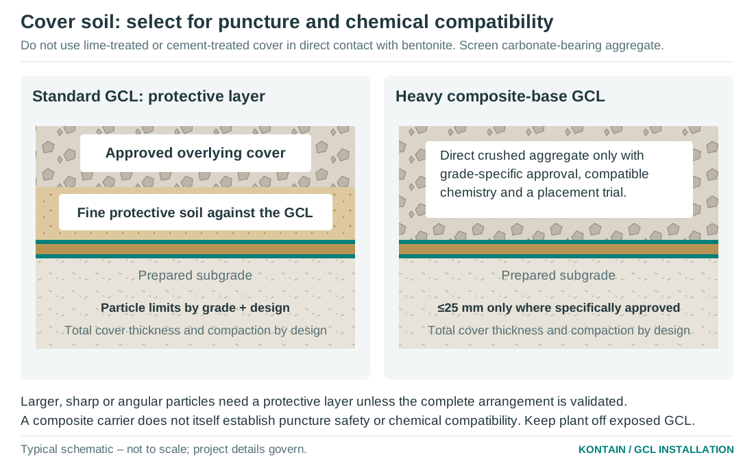
Do not use lime-treated or cement-treated soil, fresh concrete washout, or unassessed lime-bearing cover directly against conventional sodium-bentonite GCL. High dissolved calcium or magnesium can exchange with sodium and reduce swelling. High ionic strength and extreme chemistry can also affect performance.
Limestone is not the same as lime
Limestone, dolomite, gypsum, shell-rich fill and recycled concrete require chemical assessment; do not accept them merely because no lime stabiliser was added. Total carbonate content is a screening indicator, not a complete measure of the liquid that will reach the bentonite. Conversely, not all crushed rock contains limestone. Confirm the quarry source and representative soil leachate or pore-water chemistry.
What to test
- Assess subgrade, cover, groundwater, hydration water and the expected service liquor, including plausible seasonal or process changes.
- Screen pH, electrical conductivity/salinity and relevant major ions, including calcium and magnesium; add contaminants relevant to the process.
- Use representative hydraulic-compatibility testing on the proposed GCL formulation, with the intended hydration sequence, confinement and liquid. Include seams where their performance is critical.
- Agree acceptance criteria and test duration with the designer. A swell index, short exposure or fresh-water permeability certificate is not a service-life demonstration.
Polymer modification
Polymer-modified bentonite can be selected where aggressive cover-soil leachate, saline water or process liquor may contact the bentonite. Performance is formulation-specific. Confirm resistance to the actual chemistry, longevity, polymer retention and the hydration sequence. Specify matching accessory bentonite or sealant; ordinary sodium-bentonite seam material can become the weak point.
What a laminate can and cannot do
An intact PE laminate can reduce direct face exposure to water and chemicals and provide an additional barrier. Liquid can still reach bentonite at loose laps, terminations, defects and from below. Select polymer type, thickness and durability for the duty. Neither a thin laminate nor a geotextile makes incompatible contact materials acceptable.
Separating questionable rock
A compatible soil cushion can protect the liner physically and moderate immediate contact. It is not a permanent chemical isolation layer: dissolved constituents can migrate through it. Where cover chemistry is uncertain, obtain test evidence or substitute accepted material instead of relying on a nominal clay blanket.
SECTION 07
Select the contact and cover materials
Particle size, angularity, chemistry, confinement and construction load act together. There is no single maximum stone size that fits every GCL.
Proposed guide baselines - confirm in the project schedule
| Configuration | Direct contact material | Acceptance requirement |
|---|---|---|
| Standard GCL | Prefer fine, well-graded soil or selected sand/fine gravel. A 25 mm maximum is an upper screening limit, not automatic approval. | Use a smaller limit or cushion where the grade, angularity, loading or trial requires it. Remove sharp projections. |
| Heavier composite-base GCL | Crushed aggregate up to 25 mm may be placed directly on an accepted grade. | Require accepted chemistry with no lime-bearing contamination, puncture/protection assessment and a successful trial using actual aggregate, plant and lifts. |
| Laminated GCL | Follow both the GCL and PE protection requirements. | The laminate may be more vulnerable than the base GCL. Heavy base construction alone does not justify aggregate directly on a thin film. |
| Coarser, open-graded or very angular material | No general direct-contact approval. | Design a finer protective layer or suitable geotextile, and verify puncture, interface stability and placement. |
| Aggressive or saline contact materials | No default acceptance for conventional bentonite. | Test compatibility; change the material, bentonite formulation or barrier design as necessary. |
Confinement thickness
Use at least 300 mm of accepted soil cover as the general buried-system guide baseline, or the greater project requirement. This is not a traffic-bearing design. Frequent construction traffic commonly needs at least 600 mm, and heavy or repeated loading can require more. Confirm the actual plant and loading before work; a thin cover may not protect against turning, braking or vibration.
Grading and stability
Provide material that can be placed uniformly without segregation, bridging or displacement. Confirm density, moisture, drainage, filter compatibility and resistance to erosion or dispersion. Clean sand, highly plastic clay and angular crushed rock each have different risks; none is universally preferred. Do not assign long-term cohesion from appearance or dry apparent strength.
Where a cushion is used
Specify its accepted material, thickness and placement method separately. Check both sides of every added geotextile for stability. Maintain total confinement across seams, repairs, slopes and penetrations. Keep sharp erosion-control rock away from the GCL unless the complete protection system is verified.
SECTION 08
Design the slopes and anchorages
A slope ratio is a starting geometry, not a product rating. Stability must cover installation, filling, operation and drawdown.
Indicative geometries
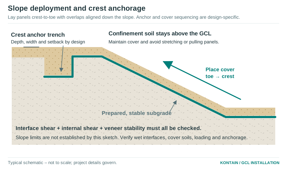
1V:4H (about 14°) is a common starting point for conventional GCL layouts, subject to design. Composite-base grades with suitable nonwoven contact faces may provide improved interface performance and may be considered for slopes as steep as 1V:2H (about 26.6°) in specifically designed cases. These are not guaranteed maximum slopes or accepted designs.
What the stability check must include
- Hydrated GCL internal shear and every interface, including PE-to-soil, geotextile-to-soil, added cushions and adjacent geomembranes.
- Representative normal stress, density, moisture, hydration history, drainage and shear displacement. Select peak, large-displacement or residual strength for the actual failure mechanism.
- Cover thickness and weight, pore-water pressure, seepage, rapid drawdown, construction loads, toe support, settlement and seismic loading where relevant.
- Long-term reinforcement behaviour, anchor-trench pull-out and the sequence of covering and filling. Do not rely on tensile strength or anchorages to stabilise an otherwise sliding cover veneer.
Granular contact layers
Well-graded granular materials above and below a composite-base GCL can be useful where friction governs. Their use must be verified with the actual exposed geotextile faces. A smooth PE laminate on top can still control stability even when the underside has high friction. Change the subgrade or cover only through an approved design; protect against puncture and confirm chemistry.
Slope installation
Use continuous panels from crest to toe with longitudinal seams running down the slope. Avoid end laps on slopes. Any unavoidable transverse joint needs a specific overlap, location, restraint and inspection detail; do not apply the flat-base end-lap value automatically. Avoid joints at abrupt crest and toe transitions.
Anchorage
Use the designed crest setback, rounded trench profile, liner run-out, backfill and compaction. Secure the panel before releasing deployment support. Keep GCL in intimate contact with the trench, without bridging or sharp folds. Inspect before backfill. Do not pin through the hydraulic liner or copy a generic trench dimension without checking pull-out and slope stability.
SECTION 09
Deploy panels without damage or tension
Plan the route for both the deployment plant and the cover plant. Each completed panel needs a clear path to inspection and protection.
Deployment sequence
- Confirm subgrade release, weather window, panel layout and the roll’s identity. Open wrapping immediately before use with controlled cuts that cannot reach the GCL.
- Verify which face belongs against the subgrade. For laminated systems the PE normally faces the contained liquid; follow the project section where the arrangement differs.
- Unroll under control from the approved lifting arrangement, usually by feeding from the underside of the suspended roll so it lays naturally. Keep plant on the approved access route.
- Place flat, with sufficient slack to conform to grade changes but without folds. Do not stretch, drag over abrasive surfaces or use soil to pull out wrinkles.
- Align overlap marks and verify the actual lap width along the complete seam. Keep edges clean and dry; complete seam treatment while accessible.
- Stagger end joints and avoid four-way intersections. At approved T-joints, maintain full contact and the required lap of every panel; provide the detail’s additional treatment or patch.
- Protect every cut with a sacrificial board or offcut underneath. Use a sharp knife; avoid cutting underlying GCL, PE or other geosynthetics. Remove all loose trimmings.
- Record the panel and roll numbers immediately. Inspect before any cover, geomembrane or detail makes the work inaccessible.
Traffic and personnel
Do not drive on exposed GCL. Keep walking to the minimum needed, with clean footwear and care around seams. Never walk on wet, slippery bentonite or use exposed GCL as an access track. Place tools on protective pads; do not push wheelbarrows or drag equipment across the liner.
Adjacent geomembranes
Place the overlying geomembrane promptly after GCL acceptance when specified. Use an approved slip sheet or handling method where textured geomembrane could pull fibres or move seams. Remove temporary slip sheets unless they are part of the designed system. An overlying membrane provides weather protection but does not, by itself, provide the required confinement.
Stop and correct
Stop for rain, uncontrolled wind, poor visibility, softening subgrade, misidentified rolls, damaged cores, seam contamination, bridging or tension. Mark the affected area and obtain the required inspection. Cover placement is not a repair method.
SECTION 10
Form unlaminated GCL overlaps
The hydraulic joint relies on clean geotextile-to-geotextile contact, enough overlap, the correct bentonite treatment and continuous confinement.
General seam schedule
| Location | Guide baseline | Treatment |
|---|---|---|
| Factory longitudinal edge | At least 300 mm actual overlap. | An ordered and accepted self-sealing factory edge needs no additional site bentonite where its approved detail states this. |
| Roll ends and field-cut seams on a base | At least 600 mm actual overlap. | Apply the approved accessory bentonite treatment; cut edges are not automatically self-sealing. |
| Approved end seam on a slope | Project-specific; avoid where practicable. | Designer defines larger overlap, restraint, location and treatment. |
| Repairs | Patch extends at least 500 mm beyond all damage. | Approved perimeter treatment, full contact and inspection. |
| Penetrations and structures | Use the issued detail. | Compatible bentonite/sealant, collars and confinement; see detail sections. |
Self-sealing long edges
Check the factory treatment is present, intact, correctly orientated and identified in the supplied product documentation. The self-sealing mechanism activates as bentonite hydrates under confinement. It does not seal a gap, contaminated overlap, displaced panel or unconfined edge. Do not assume both sides, both ends or every product family carries the same treatment.
Making the lap
- Remove soil, debris and standing water without stripping bentonite or damaging fibres. Do not brush away an embedded factory treatment.
- Overlap to the accepted width and keep the contact surfaces flat. Shingle upper/upgradient panels over lower/downgradient panels where drainage and placement direction require it.
- At untreated seams apply compatible accessory bentonite in the continuous band and quantity specified for the grade. Obtain the accepted rate before starting; do not substitute an unverified application rate.
- For treated seams record the accessory lot, mass used and length treated. Recheck after wind or panel adjustment. Keep material out of drains and underdrain geocomposites.
- Inspect lap width, continuity, orientation and cleanliness before cover. Do not use nails, staples or through-pins to hold the hydraulic seam.
Bentonite paste
Use paste only where the approved detail permits it, with the specified compatible bentonite, water and mix ratio. Do not substitute slurry for a required dry seam treatment or use uncontrolled site mixing. Paste availability and formulation must be confirmed with the order; polymer-modified systems may need a matched proprietary accessory.
SECTION 11
Use the supplied laminate overlap detail
The published laminate options are 0.2 and 0.5 mm PE. Use the accepted product and project joint detail.
Maintain the intended barrier contact
Maintain the specified direct GCL contact, seam treatment and continuous compatible confinement. Confirm the manufacturer’s longitudinal and end-joint details before deployment. Do not cut or strip a bonded laminate to improvise an overlap.
Match the design duty
A loose laminate lap is not a continuous field-welded geomembrane. If the design requires a separate welded membrane, specify and detail that layer independently. Resolve unsuitable joints before procurement or installation.
SECTION 12
Control weather and premature hydration
Deploy only what can be seamed, inspected and protected within the available weather window. Lamination improves face protection but does not remove weather risk.
Conditions for deployment
- Do not deploy in rain, standing water, snow or ice, onto frozen or softened subgrade, or where runoff can enter beneath the liner.
- Stop when wind prevents safe lifting, panel control or clean seam treatment. Use the lifting plan’s limits; a roll is a large sail.
- In hot, dry weather, limit exposure and inspect for curling, shrinkage and PE movement. In cold conditions, follow the material and welding procedure limits; never handle a frozen hydrated GCL as if it were a dry roll.
- Arrange drainage and daily work limits so accepted panels can normally be covered in the same shift. Do not leave unprotected work overnight.
If rain is forecast or work pauses
Complete and inspect the accessible seams, then place permanent cover where possible. Protect unfinished edges, ends, penetrations and stored rolls with secure waterproof sheeting that sheds runoff away. Extend protection around leading edges to prevent water entry beneath. Use smooth ballast or sandbags that cannot puncture the liner; do not drive stakes through it. Temporary sheeting is not permanent confinement.
How laminate helps
An intact PE face reduces direct rain entry and evaporation through that face and can reduce wet-dry exposure of the bentonite. Water can still enter through unfinished laps, exposed roll ends, defects, penetrations or from the subgrade. Thin PE can also be damaged by wind, handling and traffic. Inspect the whole detail, not just the apparently dry top face.
After unexpected wetting
- Stop deployment and isolate the affected area. Do not drag, lift, traffic or conceal swollen or slippery GCL.
- Check bentonite loss, extrusion, delamination, displaced overlaps, trapped water, soft subgrade and contaminated seams. Inspect hidden low points and likely flow paths.
- Have the nominated inspector and designer determine whether the material remains acceptable, can be confined promptly, needs repair or must be replaced. A damp appearance alone does not decide acceptance.
- Record the event, extent, photographs and written disposition. Reinspect seams and subgrade after temporary covers are removed and before permanent cover.
Keep water out of the system
Do not deliberately pre-wet exposed GCL to speed work. Avoid repeated wet-dry cycling and long exposure beneath an unconfined geomembrane. Keep runoff carrying bentonite away from surface water, drainage layers and sumps.
SECTION 13
Place and compact confinement soils
The first protective lift is critical. The objective is uniform support and confinement without moving the GCL, opening overlaps or punching stones through it.
Before the first lift
Release panels, overlaps, repairs, penetrations and any membrane welds through the agreed CQA hold point. Confirm the cover material source, chemistry, grading and moisture. Use the approved plant, lift thickness and trial method. Recheck that wind or adjacent operations have not displaced the work since inspection.
Placement method
- Keep plant on already placed cover or another designed working platform. Maintain the accepted minimum separation beneath tracks, wheels and blades at all times.
- Place the first lift gently. Do not end-tip sharp aggregate directly onto exposed GCL, drop large lumps, or drag a bucket or blade across it.
- Spread progressively without shoving the GCL or rolling seams. On slopes normally work from the toe towards the crest, placing or pushing cover upslope under the approved method.
- Do not turn sharply, brake hard or spin tracks on thin cover. Increase protection or change equipment if rutting, pumping, lateral movement or aggregate punching occurs.
- Maintain full thickness at seams, changes of grade, edges and structures. Keep construction heaps and stockpiles within the checked load case.
- Prevent aggregate segregation and inspect exposed leading edges repeatedly. Stop if there is evidence of displaced panels, emerging bentonite or damaged laminate.
Compaction requirements
The designer specifies the dry-density ratio, laboratory compaction reference, moisture window, lift thickness, plant, passes and acceptance testing for each soil. Standard and modified compaction are different references and must not be interchanged. Optimum moisture content is a moisture measure; dry density is a density measure.
Do not adopt a universal compaction percentage
A clay cushion at 95% of standard maximum dry density and an aggregate layer at 98% may be project choices, but they are not blanket GCL requirements. Demonstrate that the selected effort achieves the specified density without damaging the liner. Avoid heavy vibration or aggressive compaction over the first lift unless a representative trial has validated it. Do not simply increase passes where the foundation pumps.
After covering
Measure and record the minimum completed cover thickness by a method that does not puncture the GCL. Mark restricted traffic areas, protect against erosion and prevent later excavation into the liner. Any suspected installation damage requires investigation and an accepted repair before commissioning.
SECTION 14
Hydrate and commission under control
Confinement restrains swelling and supports the low-permeability bentonite seal. Commission the whole containment system, including overlaps and terminations.
Normal hydration
After acceptance and confinement, compatible moisture in the subgrade or cover may hydrate the bentonite. The available moisture, soil contact, temperature, laminate and confining stress affect the rate. Do not assign one universal hydration time or water volume to all products and sites.
Controlled prehydration
Where aggressive or non-aqueous liquid is expected, the design may require hydration with accepted clean water before service. Define water quality, application method, confinement, time and evidence of completion through compatibility testing. Prehydration can help some formulations but does not guarantee lasting chemical resistance after ion exchange or repeated exposure.
Laminated systems
A laminate can slow moisture entry from its upper face, so hydration may rely more on the subgrade or deliberately detailed routes. Confirm adequate hydration without trapping free water or destabilising the cover. Do not puncture the laminate to introduce water or use process liquor for initial hydration unless the design and tests support it.
Before filling or process service
- Close all installation non-conformances and approve the as-built panel plan, repairs, CQA records, cover thickness and any weld testing.
- Verify penetrations, valves, sumps, terminations and interfaces with concrete or other liners are complete and accessible for the required checks.
- Confirm erosion protection, overflow routing, groundwater/gas relief and the minimum confining pressure for every operating water level.
- Fill or introduce liquid at the design-approved rate. Inspect settlement, seepage, cover movement and unusual turbidity or bentonite migration.
- Do not remove cover, draw down rapidly or allow the system to dry out contrary to the design. Maintain restrictions on traffic and excavation.
Operation and maintenance
Keep an as-built liner plan available to operators. Inspect after major rain, filling/drawdown cycles and maintenance works. Repair erosion before confinement is lost. Manage vegetation and roots for the design, prevent burrowing damage where relevant, and use a controlled permit before digging near the liner. A future repair must restore the GCL, laminate if present, and cover system.
Uplift and gas
A GCL does not eliminate uplift from groundwater or gas beneath the liner. Provide relief or ballast only as designed, with filter and drainage details that do not form uncontrolled leakage paths. Stop commissioning if uplift, heave or loss of contact occurs.
SECTION 15
Detail penetrations through slopes
The typical detail shows a horizontal pipe crossing an inclined lined embankment. Support the pipe, liner, collar and boot continuously; do not leave open voids or an unsupported liner transition.
Typical sloping-face penetration sequence
- Install and support the pipe through the embankment. Compact the trench and form a smooth supported slope around it; allow for pipe movement, thrust and differential settlement.
- Form the designed annular seal pocket at the pipe/liner crossing. Fill it fully with compatible bentonite or the specified sealant; it is a seal, not a pipe support.
- Use the approved product-specific collar detail to maintain the specified GCL contact around the pipe. Fit the collar flat, apply the compatible bentonite treatment and maintain the issued overlap.
- For laminated products, obtain a supported, compatible product-specific penetration and termination detail. Maintain the required GCL contact and do not strip bonded film to improvise a connection.
- Select the penetration detail for the supplied thin laminate or unlaminated GCL. Any separate geomembrane needs its own designed termination and installation procedure.
- Place confinement around the pipe and over the slope without impact or dragging the collar. Support the boot transition as detailed and photograph each hidden stage before covering.
Collar and support dimensions
Use the issued penetration drawing for collar extent, seal-pocket geometry, supporting material and clamp/boot dimensions. A collar extending at least 300 mm beyond a cut is a general starting detail only; movement, hydraulic head and the actual slope/pipe intersection can require more. A bentonite collar alone is not a pressure-rated pipe seal.
Other penetration arrangements
Vertical risers, inclined pipes, corrugated pipes and irregular penetrations require their own sections. Do not use a smooth-pipe detail on corrugations or cable bundles. Use a designed smooth sleeve, puddle flange or other suitable transition, and address water tracking along the trench separately.
Inspection before concealment
Check complete pipe support, the packed annular seal, direct collar-to-GCL contact, laminate continuity, clamp/flange engagement, movement allowance and confinement. Test any welds as specified. Do not accept a detail from its visible top surface alone.
SECTION 16
Terminate at concrete and other liners
A termination must prevent water bypassing the GCL and accommodate movement. Anchoring an edge and sealing an edge are different functions.
Concrete interface
- Use sound, cured and suitably prepared concrete. Remove laitance, sharp projections and contamination; repair voids and honeycombing.
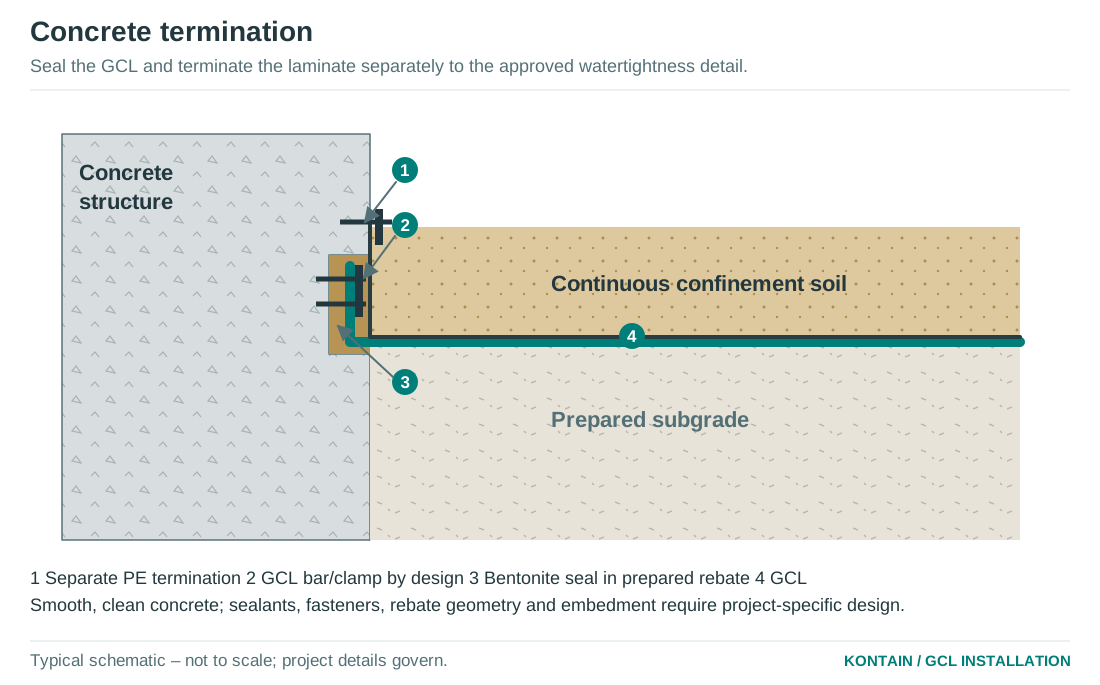
- Provide the designed rebate, chase or bentonite seal pocket. Do not place conventional bentonite directly against fresh cementitious contamination or washout.
- Continue GCL into the accepted termination with direct contact and compatible bentonite or sealant. Use the specified mechanical termination, gasket or clamping arrangement where required.
- For laminated GCL, terminate the PE separately to an approved cast-in profile, flange, batten/boot or compatible membrane connection. A bentonite strip is not a PE weld.
- Locate fixings only within the designed termination zone. Do not puncture the field liner to solve a fitting problem.
- Maintain cover/confinement up to the termination, protect the exposed edge and allow for differential movement.
Other transitions
Connections to existing GCL, separate geomembranes, sumps, anchor trenches and drainage structures require a specific detail. Confirm the existing material is identifiable, sound, clean and compatible. Define how the mineral barrier and polymer barrier each remain continuous. Do not rely on unverified adhesive tape as the hydraulic seal.
Corners and changes in level
Avoid excessive folding and stacked ridges. Use shaped panels and approved patches to maintain contact. Stagger joints away from concentrated stress and water flow. Where a vertical face cannot retain permanent confinement, use a separately designed system rather than adapting a buried-earth detail.
Hold point
Inspect the prepared substrate, seal pocket, GCL contact, membrane termination, fixings, movement allowance and confinement in sequence. Record photographs before each hidden layer. Where a structure joint can move or transmit water, its own waterstop and joint-seal design must also be complete.
SECTION 17
Repair defects and manage departures
Mark defects while they are visible. A patch must restore the hydraulic function and support of the complete system.
GCL damage
- Record the location and roll number; photograph the defect and identify its cause. Remove sharp objects and correct the subgrade or handling issue before repair.
- Use an accepted patch of the same specified construction and compatible bentonite formulation. Extend at least 500 mm beyond the full damaged area in all directions, or farther if required by the project.
- Place the patch flat with the correct orientation and direct GCL contact. Apply the specified compatible accessory bentonite continuously around the affected area beneath the patch.
- Keep patch corners and transitions flat, without folds or bridging. Repair any field cuts used for access. Record dimensions and accessory quantities.
- Replace the panel or obtain an engineered repair where there is widespread hydration damage, bentonite loss, contamination, distortion or an uncertain extent of damage.
Laminated GCL repairs
Assess GCL and thin PE laminate damage separately. Use the approved product-specific repair to restore the specified GCL contact and laminate coverage. A patch over intact PE does not create GCL-to-GCL contact through it. Do not strip bonded film or cut fibres to improvise access; replace affected material where a sound repair cannot be formed.
Seam movement or contamination
Reopen only dry, controllable seams where this can be done without damage. Restore the correct overlap and treatment, then reinspect. Hydrated seams, missing factory treatment, inadequate flap width or peeled laminates need a recorded disposition. Do not accept an under-width lap on the assumption that bentonite will swell across the gap.
Damage found after covering
Isolate traffic and agree an excavation method that will not enlarge the defect. Expose enough surrounding liner to verify the extent, restore the full detail, inspect and replace cover under the accepted method. Document the repaired position on the as-built plan.
Non-conformance control
Record the requirement, observed departure, affected area, proposed repair and approving person. Close it only after inspection and any required re-testing. Installer convenience is not an engineering approval. Do not conceal unresolved damage or substitute a different grade, seam accessory or cover material without acceptance.
SECTION 18
Inspection hold points and records
CQA records connect the delivered roll to the installed panel and the finished confinement. Keep them current each day.
Minimum hold-point schedule
| Hold point | Accept before proceeding | Record |
|---|---|---|
| Delivery | Identity, dimensions, gross mass, core and wrapping; dry and undamaged condition. | Roll register, certificates, photos, quarantine decisions. |
| Subgrade | Levels, smooth support, drainage, chemistry, compaction and moisture. | Area release and test references. |
| Trial | Actual aggregate, GCL, plant, lift and compaction method perform without damage. | Trial method, exposure inspection and acceptance. |
| Panels and seams | Orientation, overlap, factory treatment, specified GCL contact and compatible accessories. | Panel plan, seam log, widths and photos. |
| Details and repairs | Approved geometry, sealing, movement allowance and membrane integrity. | Detail/repair log and inspection stages. |
| Welds, if specified | Trials, visual acceptance, required non-destructive and destructive results; repairs closed. | Weld map and testing records. |
| After weather | No unacceptable swelling, displacement, contamination, washout or softened foundation. | Event, inspection and disposition. |
| Cover release | All hidden work accepted; material, thickness and method confirmed. | Signed area release, placement record. |
| Commissioning | Complete confinement, as-built records, closed departures and hydration plan. | CQA completion and designer/owner release. |
Daily record
Record date, work area, weather, roll/lot and panel IDs, seam and patch locations, edge treatment, actual lap widths, accessory lots/quantities, weld records, inspection decisions, photographs, cover material and minimum thickness, plant used, and the time between deployment and covering. Include any temporary protection and reinspection.
Testing framework
Use recognised current methods as applicable: ASTM D5888 for storage/handling guidance; ASTM D6102 for installation guidance; ASTM D6243 for GCL internal/interface direct shear; ASTM D6766 for hydraulic performance with potentially incompatible liquids; and ASTM D5887 for index flux. Verify the applicable edition, scope and project acceptance requirements. Listing a method is not a declaration of compliance.
SECTION 19
Site checklist and quick decisions
Use this page at the pre-start and before releasing an area to cover. The project inspection and test plan remains the controlling record.
Before deployment
- Correct grade, laminate and bentonite formulation; approved TDS and seam detail available.
- Actual roll mass and core checked; lifting gear, plant radius and access accepted.
- Subgrade inspected and released; chemistry and drainage confirmed.
- Forecast, daily area, crew, CQA and cover resources aligned.
- Accepted cover material, thickness, plant and compaction trial confirmed.
Before concealment
- Panel IDs recorded; liner flat, supported, untensioned and undamaged.
- Side and end laps measured; factory treatment intact or correct accessory treatment applied.
- Laminated joints maintain the specified GCL contact and the supplied overlap arrangement.
- Welds, penetrations, terminations and repairs inspected and tested where specified.
- Weather-related areas reinspected; no unresolved hydration or subgrade damage.
- Continuous cover and plant separation maintained; release signed before work is hidden.
Quick decisions
| Question | Action |
|---|---|
| Can crushed aggregate touch the GCL? | Only for the accepted grade and tested contact/placement system. No lime-bearing contamination; verify chemistry, particle shape and puncture risk. |
| Is a composite base suitable at 1V:2H? | Possibly, through project design and hydrated internal/interface tests. The family name alone is insufficient. |
| Are all overlaps self-sealing? | Only accepted factory-treated edges as detailed. Ends, cuts and repairs need the approved accessory treatment. |
| Can a damp roll or panel be used? | Isolate and inspect. Acceptance depends on hydration, integrity, bentonite retention and ability to confine. |
| Can lime-bearing rock sit above a clay cushion? | A cushion is not proof of chemical isolation. Test the contact system or change the material. |
Need a project-specific detail?
Send Kontain the liner section, slope geometry, liquid chemistry, soil grading and quarry source, loading/plant, penetration drawings and the selected GCL. We can help define the product evidence and installation detail needed for the designer’s review. Contact ben.lewis@kontainsolutions.com or Call Kontain.
SECTION 20
Technical requirements and document control
Use current standards and the supplied grade’s accepted evidence with the project drawings. A referenced standard is not a product approval.
Documents needed before construction
The approved project specification, drawings, installation method, order-specific TDS, seam schedule and CQA plan establish the work requirements. Confirm the GCL construction, bentonite formulation, contact soils, hydration water, service liquid and any laminate before procurement.
Guide baselines and original details
Lap, patch and cover dimensions in this guide are general baselines requiring adoption in the project and order documents. The drawings are original typical schematics, not construction drawings. Penetrations through slopes, anchorages, chemical compatibility and interface stability require the project conditions and acceptance criteria.
Contact
Kontain Pty Ltd • Geosynthetic supply and technical support • Australia-wide. kontainsolutions.com • ben.lewis@kontainsolutions.com • Call Kontain.
Linked sources
- GRI-GCL3: GCL manufacturing quality-control framework ↗
Use the applicable construction category and current project specification.
- Kontain GCL systems ↗
Product selection, installation guidance and order-specific technical support.
- Kontain liner design support tools ↗
Preliminary support; project-specific design and verification remain required.